Bridge Erection Machine
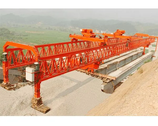
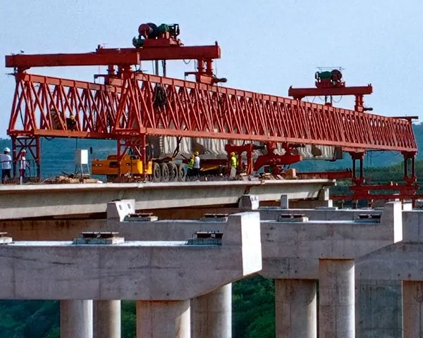
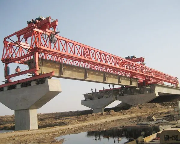
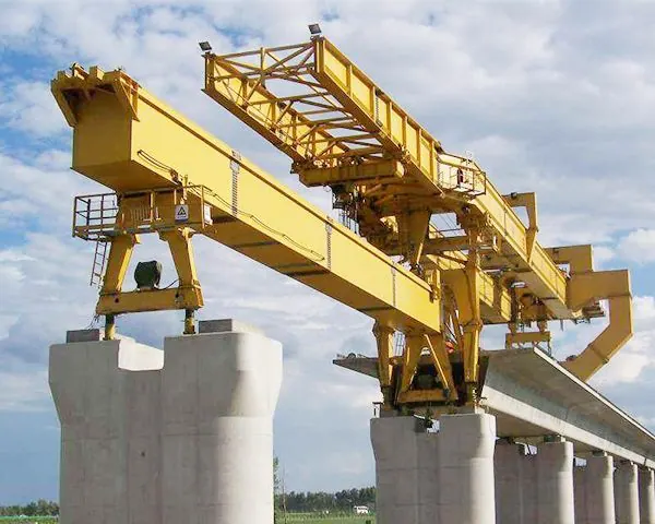
The machine arm is the main load-bearing beam of the bridge erecting machine.
Product description
Arm:
The machine arm is the main load-bearing beam of the bridge erecting machine. It is a double box girder structure. According to the stress working conditions of the machine arm and finite element analysis and calculation, each box girder is designed with a box-shaped variable cross-section. The total length is 66.0m, and the box girder is 3.0m high, divided into six segments; the center distance between the two main beams is 9m, and the segments are connected by high-strength bolts. After the segments are disassembled, they can be transported by road or rail.
The upper cover of the machine arm is laid with a track for the lifting trolley, and the lower flange plate between the first and second columns and the bottom of the lower cover are provided with tracks for the support of the first column and the hanging wheel. The machine arm is fixedly connected to the second and third columns through high-strength bolts. The first column can move relative to the machine arm when moving longitudinally. When erecting the beam, it is articulated with the machine arm through the supporting wheel set and positioning device.
The two ends of the machine arm are connected together through horizontal connections, and the second and third columns are fixedly connected to the machine arm through high-strength bolts. The No. 1 column can move relative to the machine arm when moving longitudinally. When erecting the beam, it is fixedly articulated with the machine arm through the node positioning device. The second and third columns are connected using a saddle-shaped cross connection, which can further improve the lateral connection stiffness between the machine arms. The saddle-shaped structure can not only ensure the passage of the lifting trolley, but also improve the lateral integrity of the entire machine.
The lifting trolley traveling track is laid on the upper cover of the machine arm, and the lifting trolley guide track is provided on the inside of the upper cover; the traveling ear beam of the first pillar is arranged on the lower cover in front of the second pillar. The lower cover plate at the front of the machine arm is equipped with a variable-span node, which provides different installation positions for the No. 1 column to meet the needs of 32m, 24m, and 20m box girder erection operations. When the bridge erecting machine is moving longitudinally, the No. 1 column can run forward and backward along the lower ear beam of the machine arm. When erecting the beam, it is fixedly articulated with the machine arm through the node positioning device.